
on video adjustable or Variable Power Supply Circuit Diagram (0-30V)
List of Components Used
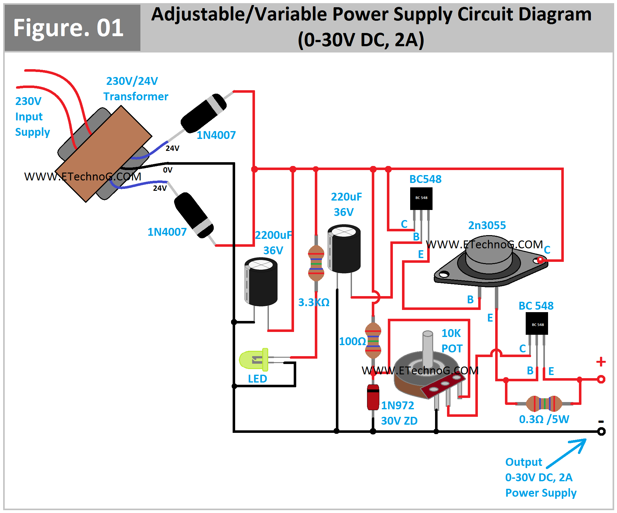
A 230V/24V center-tapped step-down transformer
2pcs 1N4007 PN Junction Diode
1pcs 2200uF, 36V Electrolytic Capacitor
1pcs 220uF, 36V Electrolytic Capacitor
1 Pcs 3.3 Kiloohm Resistor
1 Pcs 100 ohm Resistor
1 pcs 0.3ohm, 5 watt resistor
1 Pcs 10 Kiloohm Potentiometer
1pcs 30V Zener Diode(1N972)
2pcs BC548 Transistors
1pcs 2n3055 transistor
1pcs LED
Connection Procedure
Connect two 1N4007 Diodes to the output 24V terminals of the transformer and short their cathode terminals and this will be the positive output of the rectifier.
The 0V terminal of the transformer will be the negative terminal of the rectifier.
Connect the 2200uF, 36V Capacitor in parallel with the output of the rectifier circuit.
Connect the LED across the output of the rectifier circuit in series with the 3.3 Kilo Ohm resistor.
Connect the Zener diode in reverse bias across the output of the rectifier circuit through the series resistor of 100 ohms.
Connect the cathode terminal of the Zener diode to any one side terminal of the potentiometer.
Connect another side terminal of the potentiometer to the negative terminal of the rectifier output.
Connect the emitter terminal of the first BC548 transistor to the base terminal of the transistor 2n3055.
Connect the emitter terminal of transistor 2n3055 to the base terminal of the second BC548 transistor.
Connect the collector terminal of the 2n3055 transistor to the collector terminal of the first BC548 transistor and finally connect it to the positive terminal of the rectifier output.
Connect the Base terminal of the first BC548 transistor to the negative terminal of the rectifier output in series with a 220uF, 36V Transistor.
Connect the collector terminal of the second BC548 transistor to the middle terminal of the potentiometer.
Connect a 0.3ohm, 5w resistor between the base and emitter terminal of the second BC548 transistor.
Now get the output power supply across the emitter terminal of the second BC548 transistor and the negative terminal of the rectifier output.
Operation and Working Principle
Here, the step down transformer step the 230V AC voltage into 24V-0V-24V AC. An the two PN junction diodes converts the AC power supply into DC power supply. The capacitor 2200uF connected in parallel with the output of the rectifier circuit removes the ripples from the DC power supply. The LED is used for the indication purpose weather the circuit has power or not. The 30V Zener diode is used to maintain the maximum 30V output voltage.
The transistor BC548 and the transistor 2n3055 is connected in the darlington mode. This is because to achieve the 2A load current. And the second transistor BC548 is used to control or vary the output voltage. When we operate the potentiometer the base current of that transistor changes so the emitter current also changes that causes to change the voltage drop across the 0.3 ohm resistor connected between base and emitter terminal, so the output voltage of the circuit also changes.
Read Also:
Circuit Diagram of Regulated Power Supply with Component Rating
Wireless Charging Block Diagram and Working Principle
SMPS Block Diagram | Switched Mode Power Supply
Float, Trickle, Boost Charging Difference and Examples
All types of Electricity Symbols - AC, DC, Variable
Thank you for visiting the website. keep visiting for more updates.
Remember that electrical is very dangerous. And all information provided in this blog is for general knowledge only. So before executing or doing any electrical related work please verify and gather authorization.
You May Also Like:
When Capacitor store more Energy Series or Parallel connection?
Why Ceramic Capacitors mostly used in Electronic Circuit than others?
Why thickness of insulation depends on Voltage not Current?
[Explained] Why Inductor block AC and Capacitor block DC?
Why NPN Transistors are mostly used than PNP Transistors?
Why White Powder Used Inside Electrical Cables?
What is Vcc, Vss, Vdd, Vee in Electronics? Differences and Full Forms
Can use of Capacitor or Power Saver device reduce our Electricity Bill?
Why Semiconductor does not obey Ohm's Law? Explained
Which connection is better for Capacitor Bank Star or Delta?
Why all Electronic Devices Works on DC not AC?
What is the Meaning of mAh in Battery? Explained
[Main] Difference Between Voltage and EMF Explained
Float, Trickle, Boost Charging Difference and Examples
Difference between Analogue, Digital, and Power Electronics
List of Components Used
A 230V/24V center-tapped step-down transformer
2pcs 1N4007 PN Junction Diode
1pcs 2200uF, 36V Electrolytic Capacitor
1pcs 220uF, 36V Electrolytic Capacitor
1 Pcs 3.3 Kiloohm Resistor
1 Pcs 100 ohm Resistor
1 pcs 0.3ohm, 5 watt resistor
1 Pcs 10 Kiloohm Potentiometer
1pcs 30V Zener Diode(1N972)
2pcs BC548 Transistors
1pcs 2n3055 transistor
1pcs LED
Connection Procedure
Connect two 1N4007 Diodes to the output 24V terminals of the transformer and short their cathode terminals and this will be the positive output of the rectifier.
The 0V terminal of the transformer will be the negative terminal of the rectifier.
Connect the 2200uF, 36V Capacitor in parallel with the output of the rectifier circuit.
Connect the LED across the output of the rectifier circuit in series with the 3.3 Kilo Ohm resistor.
Connect the Zener diode in reverse bias across the output of the rectifier circuit through the series resistor of 100 ohms.
Connect the cathode terminal of the Zener diode to any one side terminal of the potentiometer.
Connect another side terminal of the potentiometer to the negative terminal of the rectifier output.
Connect the emitter terminal of the first BC548 transistor to the base terminal of the transistor 2n3055.
Connect the emitter terminal of transistor 2n3055 to the base terminal of the second BC548 transistor.
Connect the collector terminal of the 2n3055 transistor to the collector terminal of the first BC548 transistor and finally connect it to the positive terminal of the rectifier output.
Connect the Base terminal of the first BC548 transistor to the negative terminal of the rectifier output in series with a 220uF, 36V Transistor.
Connect the collector terminal of the second BC548 transistor to the middle terminal of the potentiometer.
Connect a 0.3ohm, 5w resistor between the base and emitter terminal of the second BC548 transistor.
Now get the output power supply across the emitter terminal of the second BC548 transistor and the negative terminal of the rectifier output.
Operation and Working Principle
Here, the step down transformer step the 230V AC voltage into 24V-0V-24V AC. An the two PN junction diodes converts the AC power supply into DC power supply. The capacitor 2200uF connected in parallel with the output of the rectifier circuit removes the ripples from the DC power supply. The LED is used for the indication purpose weather the circuit has power or not. The 30V Zener diode is used to maintain the maximum 30V output voltage.
The transistor BC548 and the transistor 2n3055 is connected in the darlington mode. This is because to achieve the 2A load current. And the second transistor BC548 is used to control or vary the output voltage. When we operate the potentiometer the base current of that transistor changes so the emitter current also changes that causes to change the voltage drop across the 0.3 ohm resistor connected between base and emitter terminal, so the output voltage of the circuit also changes.
Read Also:
Circuit Diagram of Regulated Power Supply with Component Rating
Wireless Charging Block Diagram and Working Principle
SMPS Block Diagram | Switched Mode Power Supply
Float, Trickle, Boost Charging Difference and Examples
All types of Electricity Symbols - AC, DC, Variable
Thank you for visiting the website. keep visiting for more updates.
Remember that electrical is very dangerous. And all information provided in this blog is for general knowledge only. So before executing or doing any electrical related work please verify and gather authorization.
You May Also Like:
When Capacitor store more Energy Series or Parallel connection?
Why Ceramic Capacitors mostly used in Electronic Circuit than others?
Why thickness of insulation depends on Voltage not Current?
[Explained] Why Inductor block AC and Capacitor block DC?
Why NPN Transistors are mostly used than PNP Transistors?
Why White Powder Used Inside Electrical Cables?
What is Vcc, Vss, Vdd, Vee in Electronics? Differences and Full Forms
Can use of Capacitor or Power Saver device reduce our Electricity Bill?
Why Semiconductor does not obey Ohm's Law? Explained
Which connection is better for Capacitor Bank Star or Delta?
Why all Electronic Devices Works on DC not AC?
What is the Meaning of mAh in Battery? Explained
[Main] Difference Between Voltage and EMF Explained
Float, Trickle, Boost Charging Difference and Examples
Difference between Analogue, Digital, and Power Electronics


No comments