
on video What is a JFET Transistor? How Does a JFET Transistor Work? (JFET Transistor Tutorial)
In this lesson, I will explain the the structure and working principle of JFETs, which are the basis of voltage-controlled field-effect transistors used in electronic circuits switching task. As you can see here, we can study FETs in two main groups. In this lesson I will describe JFET. JFET's abbreviation consists of the initials of the words Junction Field Effect Transistor.
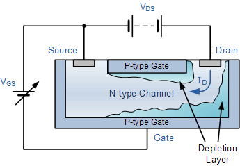
On the left, you see the shape of the JFET transistor, and on the right, the symbol. The JFET Transistor has three pins. One of them is Gate, the other one is Drain and the last one is Source. They are denoted by the abbreviations G, D and S. Their locations are not always like this, they can change. In its symbol, Gate, Drain and Source pins are like this. So how does the JFET transistor work? With a low trigger voltage coming from the Gate, a high current is controlled from Drain to Source. We can compare the JFET transistor to a faucet. The valve of the faucet is Gate and the direction of water is between Drain and Source. In other words, while controlling the current in the transistor, we can control the flow of water in the faucet. When we open the valve, we control the water.
In the symbol, if the direction of the arrow on the Gate pin shows inside it is N-Channel and if it shows outside, it is P-Channel. So what's the difference between them? To trigger N-Channel JFET, the negative pin of the connected source must be connected to the Gate of the JFET and the positive pin to the Source. The connection in P-Channel is vice varsa. The positive pin of the source must be connected to the Gate of JFET and the negative pin to the Source. This is the difference between the two types . The voltage value of the source connected between Gate and Source and the current value between Drain and Source are checked in both. So how does a JFET transistor work then, let's have a look.
Based on this example, we can easily understand the working principle of JFET. As you can see here, there is a P-Channel JFET, a small DC motor and a 12V power source to start this motor. Now let's check the speed of this motor. We supplied the motor with 12V voltage. We also linked a source between JFET's Gate and its Source, to control its speed. We can adjust the value of the current between the voltage value of this source and JFET's Drain and Source. In other words, we control the current by voltage. It should be noted here that there is never a trigger current at the Gate pin of JFET. Drain current is controlled by voltage. If you remember, we checked the current and current in the BJT transistor. In FET transistors, current is controlled by voltage. Here you can see that the voltage source connected between Gate and Source is 1V. In this way, a current flows between Drain and Source. With this current, our motor rotates at a certain speed. Let's remove the 1V voltage source. When we remove the voltage source required for triggering, no current flows between Drain and Source. Let's connect 3V voltage source instead. In this way, we can see that the motor turns slower. So, the current between Drain and Source has decreased slightly.
Be have checked this current with a voltage source. Now let's remove the 3V voltage source and connect 5V voltage source this time. Here, we can see that the motor rotates slower. This shows us that the current between Drain and Source has decreased further. JFET transistor works on this principle. We can adjust the current flowing between Drain and Source according to the intensity of the voltage we connect between Gate and Source. Now let's look at the Proteus simulation. The working principle of the JFET transistor which is a variant of the FET transistor, can be explained basically in this way.
In this lesson, I will explain the the structure and working principle of JFETs, which are the basis of voltage-controlled field-effect transistors used in electronic circuits switching task. As you can see here, we can study FETs in two main groups. In this lesson I will describe JFET. JFET's abbreviation consists of the initials of the words Junction Field Effect Transistor.
On the left, you see the shape of the JFET transistor, and on the right, the symbol. The JFET Transistor has three pins. One of them is Gate, the other one is Drain and the last one is Source. They are denoted by the abbreviations G, D and S. Their locations are not always like this, they can change. In its symbol, Gate, Drain and Source pins are like this. So how does the JFET transistor work? With a low trigger voltage coming from the Gate, a high current is controlled from Drain to Source. We can compare the JFET transistor to a faucet. The valve of the faucet is Gate and the direction of water is between Drain and Source. In other words, while controlling the current in the transistor, we can control the flow of water in the faucet. When we open the valve, we control the water.
In the symbol, if the direction of the arrow on the Gate pin shows inside it is N-Channel and if it shows outside, it is P-Channel. So what's the difference between them? To trigger N-Channel JFET, the negative pin of the connected source must be connected to the Gate of the JFET and the positive pin to the Source. The connection in P-Channel is vice varsa. The positive pin of the source must be connected to the Gate of JFET and the negative pin to the Source. This is the difference between the two types . The voltage value of the source connected between Gate and Source and the current value between Drain and Source are checked in both. So how does a JFET transistor work then, let's have a look.
Based on this example, we can easily understand the working principle of JFET. As you can see here, there is a P-Channel JFET, a small DC motor and a 12V power source to start this motor. Now let's check the speed of this motor. We supplied the motor with 12V voltage. We also linked a source between JFET's Gate and its Source, to control its speed. We can adjust the value of the current between the voltage value of this source and JFET's Drain and Source. In other words, we control the current by voltage. It should be noted here that there is never a trigger current at the Gate pin of JFET. Drain current is controlled by voltage. If you remember, we checked the current and current in the BJT transistor. In FET transistors, current is controlled by voltage. Here you can see that the voltage source connected between Gate and Source is 1V. In this way, a current flows between Drain and Source. With this current, our motor rotates at a certain speed. Let's remove the 1V voltage source. When we remove the voltage source required for triggering, no current flows between Drain and Source. Let's connect 3V voltage source instead. In this way, we can see that the motor turns slower. So, the current between Drain and Source has decreased slightly.
Be have checked this current with a voltage source. Now let's remove the 3V voltage source and connect 5V voltage source this time. Here, we can see that the motor rotates slower. This shows us that the current between Drain and Source has decreased further. JFET transistor works on this principle. We can adjust the current flowing between Drain and Source according to the intensity of the voltage we connect between Gate and Source. Now let's look at the Proteus simulation. The working principle of the JFET transistor which is a variant of the FET transistor, can be explained basically in this way.


No comments