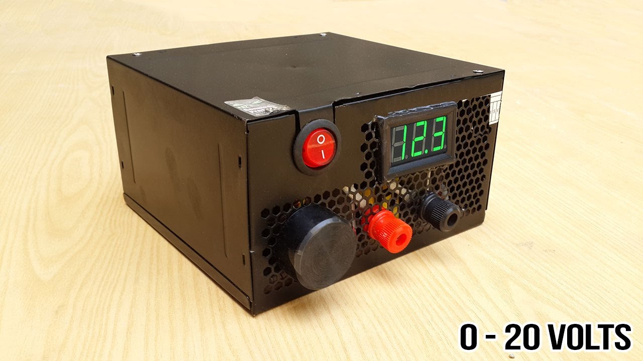
on vidio How to make adjustable 1 to 20 voltage power supply from old PSU.DIY Bench power supply.
We need different range of voltages to power any electronics like DC motors,circuits etc.So, i have made this adjustable power supply by showing a Circuit diagram to you guys and with the help of my video.It is very easy to make your own even, a begginer can also make this one by following video and circuit diagram.
ABOUT WIRING:
Here in this PSU to make it 1- 20v adjustable power supply i have cut all unecessary wires excep four wires : Blue,Yellow,Green and Grey.
Blue wire is -12v used for cathode and Yellow wire is +12v used for Anode and the remaining two are for turn the PSU on by connecting them together and for Digital DC volt meter there are three wires connected with RED,BLACK and WHITE Red&Black wires are to power the Meter connect Black to Blue -12v and Red to +12v and connect the White wire to output voltage side of circuit which is adjustable for more better understanding the circuit diagram is in the video.
MATERIAL'S LIST:
220 ohm Resister 1/4W (1)
100uF 35v Capacitors (2)
0.1 uF 50v Capacitors (2)
VR Potentiometer 10k (1)
U1 LM317 Regulator
Binding Pots (2)
Digital DC volt meter 0-99v
Volume knob
AC Switch on/off button
This is a PSU from old computer and want it to convert to 1 - 20 Volts Adjustable power supply almost works same as bench power supply.
We need different range of voltages to power any electronics like DC motors,circuits etc.So, i have made this adjustable power supply by showing a Circuit diagram to you guys and with the help of my video.It is very easy to make your own even, a begginer can also make this one by following video and circuit diagram.
ABOUT WIRING:
Here in this PSU to make it 1- 20v adjustable power supply i have cut all unecessary wires excep four wires : Blue,Yellow,Green and Grey.
Blue wire is -12v used for cathode and Yellow wire is +12v used for Anode and the remaining two are for turn the PSU on by connecting them together and for Digital DC volt meter there are three wires connected with RED,BLACK and WHITE Red&Black wires are to power the Meter connect Black to Blue -12v and Red to +12v and connect the White wire to output voltage side of circuit which is adjustable for more better understanding the circuit diagram is in the video.
MATERIAL'S LIST:
220 ohm Resister 1/4W (1)
100uF 35v Capacitors (2)
0.1 uF 50v Capacitors (2)
VR Potentiometer 10k (1)
U1 LM317 Regulator
Binding Pots (2)
Digital DC volt meter 0-99v
Volume knob
AC Switch on/off button


No comments